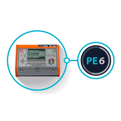
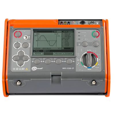
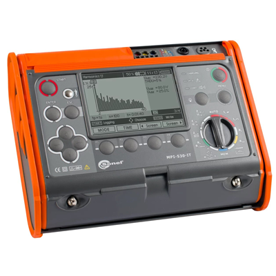
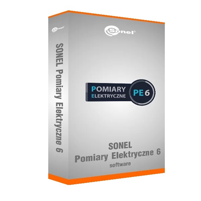
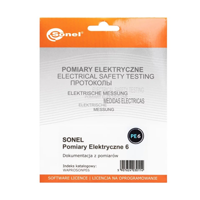
MPI-530-IT multifunction meter + license for the SONEL PE6 program WMPLMPI530ITSPE6
Popis produktu
Multifunctional electrical installation meter
Professional and versatile
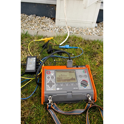
Multifunctional electrical installation meter Sonel MPI-530-IT is a response to the needs of specialists in the electrical industry, including primarily installers and measuring technicians. This extremely versatile, multifunctional device is used to measure the parameters of electrical installations and allows you to perform all measurements related to protection against electric shock, which are described in the PN-HD 60364-6 standard, in also for measurements of residual current protection in networks with an insulated neutral point of an IT transformer. The meter has been constructed in accordance with the requirements of the PN-EN 61557 standard.
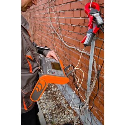
This model of the meter boasts extensive earthing measurement functions in the form of additional clamp methods and ground resistivity measurement. Using the optional AutoISO-1000C adapter, it is also possible to perform automatic insulation resistance measurements in sockets and on 3-, 4- and 5-wire cables. An additional external probe also allows you to conduct illuminance tests. In addition, the meter allows you to register and analyze network parameters, including harmonics up to the 40th order.
Sonel MPI-530-IT One advanced device includes the functions and capabilities of several measuring devices. A multitude of practical functions combined with high measurement precision makes the Sonel MPI-530-IT meter a reliable measuring instrument.
Features
The meter is characterized by < strong>broad possibilities in the field of functionality. It combines the measurement capabilities of several devices, while ensuring equally good accuracy.
- The MPI-530-IT device can be used to perform all acceptance measurements of electrical installations in accordance with applicable
- fault loop impedance (also in circuits with RCDs),
- parameters of RCDs,
- insulation resistance, < li>earth resistance (4 measurement methods + ground resistivity measurement),
- continuity of protective and equalizing connections,
- illuminance,
- phase sequence test,
- test of motor rotation direction.
- L1 voltage – average values up to 500 V,
- L1 current – average values, current measurement in the range up to 3 kA (depending on the current clamps used),
- frequency in the range of 40 Hz – 70 Hz,
- active power (P), reactive power (Q), apparent power (S),
- power factor (PF), cosφ,
- harmonics (up to the 40th in voltage and current),
- harmonic distortion factor THD for current and voltage
< strong>Inspection of installation safety
With the instrument, you can control home and industrial electrical installations in terms of safety. Measurements can be easily automated by:
- testing residual current circuit breakers in Auto mode,
- using the WS type adapter to test the installation through a standard 230 socket V.
- use of the AutoISO-1000C adapter to test the insulation resistance of 3-, 4- and 5-core wires.
Memory structure
The memory structure is in the form of a tree. It allows you to save tens of thousands of results in the CLIENT-OBJECT-ROOM-MEASURING POINT system, which helps in the subsequent creation of a transparent protocol. This structure can be prepared in the meter before starting work. Entering data into the device is facilitated by the QWERTY keyboard, which connects to it via Bluetooth.
Built-in help system
The device has built-in help screens with measurement diagrams. Thanks to this, you can easily and quickly check how to connect a given system depending on the type of measurement.
Increased resistance to environmental conditions
The meter The MPI-530-IT will cope well in harsh environmental conditions. Protection against the ingress of dust and water is provided by a unique housing with an IP54 tightness level. It is resistant to mechanical damage, and the special design allows you to easily protect the display by sliding the meter cover. In addition to the fact that it protects against damage, it also allows you to conveniently carry and use the device in various positions.
Communication and software
< p>Through the USB port or using Bluetooth wireless communication, you can transfer the measurement data to a computer. In order to generate a test report in the field of electric shock protection, use the Sonel Electrical Measurements program. Saving the downloaded resources to the simplest formats and printing them is provided by Sonel Reader.
| Measurement functions | Measurement range | Display range | Resolution | Accuracy |
|---|---|---|---|---|
| Fault loop impedance | ||||
| ZL-PE, ZL-N, ZL-L fault loop | 0.13 Ω …1999.9 Ω to IEC 61557 | 0.00 Ω…1999 Ω | da 0.01 Ω | from ±(5% m.v. + 0, 03 Ω) |
| ZL-PE fault loop in RCD mode | from 0.50 Ω…1999 Ω to IEC 61557 | 0.00 Ω…1999 Ω | da 0.01 Ω | from ±(6% m.v. + 5 digits ) |
| Measurements of RCD Parameters | ||||
| RCD tripping test and tripping time measurement tA measuring current 0.5 IΔn, 1 IΔ n, 2 IΔn, 5 IΔn | ||||
| RCD of general type and short delay | ||||
| • TN/TT network | 0ms…300ms | 0ms…300ms | 1ms | ±(2% m.v. + 2 digits) |
| • IT network | 0ms…400ms | 0ms…400ms | 1ms | ±(2% m.v. + 2 digits) |
| RCD selective | 0 ms…500 ms | 0 ms…500 ms | 1 ms | ±(2% m.v. + 2 digits) |
| Measuring RCD trip current IA measuring current 0.2 IΔn…2.0 I&Delta ;n | ||||
| 3.3 mA…1000 mA | 3.3 mA…1000 mA | da 0, 1 mA | ±5% IΔn | |
| for 1-way and 1-way differential current with bias 6 mA DC (type A) | 3.5mA…700mA | 3.5mA…700mA | is 0.1mA | ± ;10% IΔn |
| for DC residual current (type B) | 2.0 mA…1000 mA | 2.0mA…1000mA | da 0.1mA | ±10% IΔn |
| Ground Resistance | ||||
| 3- and 4-wire method | from 0.50 Ω…1.99 kΩ to IEC 61557-5 | 0.00 Ω…1.99 kΩ | da 0.01 Ω | from ±(2% m.m. + 3 digits) |
| 3-wire method + clamp | 0.00 Ω…1.99 kΩ | 0.00 Ω…1.99 kΩ | will give 0.01 Ω | ±(8% m.v. + 4 digits) |
| 2-clamp method | 0.00 Ω…99.9 kΩ | 0.00 Ω…99.9 kΩ< /td> | da 0.01 Ω | from ±(10% m.v. + 4 digits) |
| Soil resistivity< /strong> | 0.0 Ωm…99.9kΩm | 0.0 Ωm…99.9kΩm | da 0.1 Ωm | Depends on RE measurement accuracy |
| Insulation resistance | ; | |||
| Measuring voltage 50 V | 50kΩ…250MΩ according to IEC 61557-2 | 0 kΩ…250 MΩ | is 1 kΩ | from ±(3% m.v. + 8 digits)< /td> |
| Measuring voltage 100 V | 100 kΩ…500 MΩ according to IEC 61557-2 | 0 kΩ…500 MΩ | is 1 kΩ | from ±(3% m.v. + 8 digits)< /td> |
| Measuring voltage 250 V | 250 kΩ…999 MΩ according to IEC 61557-2 | 0 kΩ…999 MΩ | is 1 kΩ | from ±(3% m.v. + 8 digits)< /td> |
| 500 V test voltage | 500 kΩ…2.00 GΩ to IEC 61557-2 | 0 kΩ…2.00 GΩ | for 1 kΩ | from ±(3% m.v. + 8 digits ) |
| Measuring voltage 1000 V | 1000 kΩ…9.99 GΩ per IEC 61557-2 | 0 kΩ…9.99 GΩ | for 1 kΩ | from ±(3% m.v. + 8 digits ) |
| Resistance of protective and equalizing conductors | ||||
| Continuity measurement of protective and equipotential bonding with ±200 mA | < td>0.12 Ω…400 Ω to IEC 61557-40.00 Ω…400 Ω | da 0.01 Ω | ±(2% m.v. + 3 digits) | |
| Low current resistance measurement | 0.0 Ω…1999 Ω | 0.0 Ω&hellip ;1999 Ω | da 0.1 Ω | ±(3% m.v. + 3 digits) |
| Illuminance | ||||
| Lux measurement (lx) | 0 lx…399.9 klx | 0 lx…399.9 klx | da 0.001 lx | from ±(2% m.v. + 5 digits) |
| Fc measurement | 0 fc…39 .99 kfc | 0 fc…39.99 kfc | is 0.001 fc | from ±(2% m.v. + 5 digits) | < /tr>
| Phase Sequence Indication | Assisting, Inverse, UL-L Voltage: 95V…500V (45Hz…65Hz) |
< p>Specification – 1-phase recorder
The device is designed to work in networks:
- with a rated frequency of 50/60 Hz
- with a rated voltage : 110/190V, 115/200V, 127/220V, 220/380V, 230/400V, 240/415V
Network layouts supported:
< ul>| Parameter | Measurement range | Maximum resolution | Accuracy |
|---|---|---|---|
| Alternating voltage (TRMS) | 0.0…500V | 0.1V | from ±(2% m.v. + 2 digits) |
| depending on the clamp* | 0.1 mA | from ±( 5% m.v. + 3 digits) (error does not include clamp error) | |
| Frequency | 45.0…65 .0Hz | 0.1Hz | ±(0.1% m.v. + 1 digit) |
| Active, reactive and apparent power | 0 VA…1.5 MVA, 0 W…1.5 MW, 0 var…1.5 Mvar | 1 VA, 1W, 1var | from ±(7% m.v. + 3 digits) |
| cosφ and power factor (PF) | 0.00…1.00 | 0.01 | Accuracy is not specified |
| Harmonics | |||
| Voltage | 0.0…500V | 0.1V | from ±(5% m.v. + 3 digits) |
| Current | depending on clamps* | same as AC True RMS | from ±(5% m.v. + 3 digits) (accuracy does not include clamp error |
| THD | |||
| Voltage | 0.0…999.9 % (relative to first harmonic) | 0.1% | ±5% |
| Current | 0.0…999.9% (relative to first harmonic) | 0.1% | ±5% (accuracy does not include clamp error) |
- F-1A, F-2A, F-3A clamps: 0…3000 A AC (10,000 Ap-p)
- C clamps -3: 0…1000 A AC (3600 Ap-p)
- C-6A clamp: 0..10 A AC (36 Ap-p)
Alternating current (True RMS) measurement with clamps
| C-3 | C-6A | F-1A | F-2A | F-3A | |
|---|---|---|---|---|---|
| Rated current | 1000A AC | 10A AC | 3000A AC | 3000A AC | 3000A AC |
| Frequency | 30 Hz…10 kHz | 40 Hz…10 kHz | 40 Hz…10 kHz | 40Hz…10kHz | 40Hz…10kHz |
| Max. diameter of the measured cable | 52 mm | 20 mm | 380 mm | 250 mm | 140mm |
| Minimum Basic Accuracy | ≤0.3% | ≤1% | 1% | 1% | 1% |
| Battery powered | - | - | - | - | - |
| Cable length | 2m | 2.2m | 2.5m | 2.5m | 2.5m |
| Measurement Category | III 600V< /td> | IV 300V | IV 600V | IV 600V | IV 600V |
| Enclosure rating | IP40 | IP40 | IP67 | IP67 | < td>IP67
Program for creating protocols from installation security tests
The latest version of the popular program for creating protocols from electrical measurements. PE6 simplifies the documentation process. It minimizes its time. It automates. All thanks to numerous built-in mechanisms, tools and functions.
Program features:
- compliance of the printed protocol with the new standards PN-HD 60364-6:2016-07, PN-HD 60364-4-41:2017-09
- cooperation with SONEL S.A. meters,
- tree structure of the document,
- extensive databases of protections and measurement points,
- automatic calculation of required values,
- automatic evaluation of resultsó in measured values,
- schedule of measurements,
- inserting photos and drawings to protocols,
- printing measurement controls and descriptive labels for tables,
- calculation of performed measurements,
- printing invoices,
- automatic completion of protocols with a series of data.
The program supports creating documentation after tests in the field of comprehensive control of measurement points and:
- the effectiveness of automatic tripping (TN-S, TN-C, TN-C-S, TT, IT), < li>parameters of RCDs,
- circuit insulation condition (TN-S, TN-C, TN-C-S, TT, IT),
- cable insulation condition electrical wiring,
- the condition of the lightning protection system and grounding,
- wire continuity,
- insulation resistance of short-circuited and open-circuit motors,
- resistance of contactors,
- resistance of circuit breakers,
- transformer devices.
Hardware requirements:
- Operating system: Windows 10
- Minimum resolution: 1024x768
- Recommended resolution: 1920x1080
Technické údaje
-
ModelMPI-530-IT PE6
-
HiddenMPI Summer 2023
Podrobnosti o výrobci
-
VýrobceSONEL SPÓŁKA AKCYJNA
-
Adresa58-100 UL. STANISŁAWA WOKULSKIEGO 11
-
E-mail
-
DIČ8840033448


