91844
0
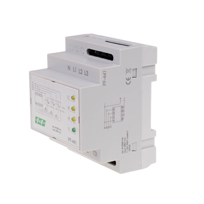
Automatic phase switch PF-441 PF-441
Product description
Intended use
The automatic phase switch is used to maintain the continuity of power supply to a single-phase receiver in the event of a power phase failure or its parameters below the standard.
Operation< br />The switch in direct connection is used to power a single-phase circuit, the load of which does not exceed 16A. For circuits with a load above 16A, we use a system of a switch and three contactors with a properly selected load capacity.
The input of the switch (L1, L2, L3, N) is supplied with three-phase voltage (3×230V+N). Single-phase voltage (230VAC) is directed to the switch output (T1, T2, T3), i.e. the phase voltage of one of the phases. The electronic system of the switch controls the voltage values of the supplied phases. The phase with correct parameters is directed to the output. The L1 phase is the priority phase, i.e. if its parameters are correct, this phase will always be connected to the output. In the absence of correct voltage parameters in the L1 phase or its decay, the electronic system will switch the L2 phase to the output (provided that its parameters are correct). If the correct voltages in the L1 and L2 phases are absent at the same time, the L3 phase will be switched on at the output. If the correct supply voltage is restored in the L1 phase, the system will switch on this phase to the output. The switching time (appearance of voltage at the output) after the decay of the currently switched-on phase is from 0.5 to 0.8 seconds (during this time the receivers are not powered). The Uk input is used to control the connected voltages. The system allows only one phase to be switched on. This prevents the simultaneous application of voltages of two phases to the output, which could cause a phase-to-phase short circuit. Also, in the event of a contactor damage (e.g. a break in the coil circuit, suspension or burnout of the working contact), it will switch the receiver to another phase, even though the voltage in a given phase is correct. In the event of a permanent short-circuit of the contactor contacts, the system will not switch over to another contactor despite the incorrect voltage in this phase. After switching on the supply voltage (at least one phase), the system checks the correctness of the connected voltages for 2 seconds and only after this time will it switch the phase to the output. LEDs are used for optical signaling: green - power supply; yellow - active phase on the output.
Technical data
-
Voltage measurement error [%]1
-
InstallationOn the TH-35 rail
-
Actuation threshold - upper [V]250
-
Signaling of the selected phase3×LED yellow
-
Working temperature [°C]-25-50
-
Package height [mm]150
-
Package weight [kg]0.25
-
Load current - system with contactors [A]For the load capacity of contactor contacts
-
Actuation threshold - lower [V]195
-
PKWIU27.12.24.0
-
Hysteresis [V]5
-
Input voltage [V]3×230V+N
-
connection1.5mm screw terminals
-
Power indicationLED green
-
Dimensions4 modules (70mm)
-
Package width [mm]90
-
Switching time[s]0.5-0.8
-
Load current - direct connection system [A]<16
-
Voltage measurement error [%]1
Other technical data
-
Type of electric connectionScrew connection
-
Rated control supply voltage AC 50 Hz0 ... 0 V
-
Phase sequence monitoringNo
-
Function under voltage detectionYes
-
Phase imbalance monitoringNo
-
Number of contacts as normally closed contact0
-
Number of contacts as change-over contact0
-
Height75 mm
-
With detachable clampsNo
-
Voltage type for actuatingAC
-
Phase failure detectionYes
-
Function over voltage detectionYes
-
Voltage measuring range195 ... 250 V
-
Number of contacts as normally open contact3
-
Width70 mm
-
Depth110 mm
Manufacturer details
-
ManufacturerF&F FILIPOWSKI SPÓŁKA KOMANDYTOWA
-
Address95-200 UL. KONSTANTYNOWSKA 79/81
-
E-mail
-
Tax identification number7310005314
Bulk packaging
| A kind of package | Sztuka |
| Quantity | 1 pcs. |
| Weight (kg) | 0,177 |
| Width (m) | 0,071 |
| Length (m) | 0,095 |
| Depth (m) | 0,070 |


